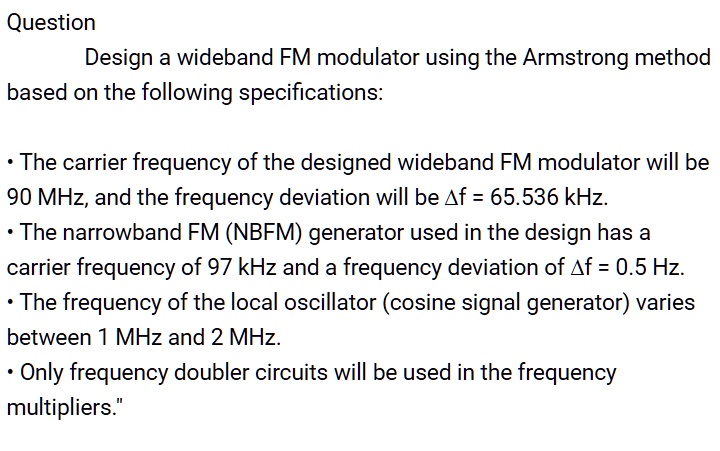
Question Design a wideband FM modulator using the Armstrong method Circuit Diagram
BlogQuestion Design a wideband FM modulator using the Armstrong method Circuit Diagram Frequency Adjustability: Adding variable capacitors and inductors to fine-tune the transmission frequency. Circuit Breakdown: Crystal Oscillator: Provides a stable carrier frequency that is less prone to drift. Modulation and Amplification: Similar to the two-transistor design but with additional stages for better performance. Next, we can adjust the C5 in the frequency generator circuit. To control the frequency from 87MHz to 108 MHz. And the frequency of the incoming sync with the frequency of the generator itself. Therefore, the frequency deviation of the signal received from the antenna to the audio signal. Which the frequency modulation is across the VR1 + R5. modulation. Your car radio receives the electromagnetic waves, converts them to electrical signals, separates the audio and radio signals, and sends the audio signal to your speakers. Radios use one of two methods to "mix" audio frequency sounds into a radio signal. They are frequency modulation (F.M.) and amplitude modulation (A.M.).

This tutorial explains circuit designing using a 555timer to generate a frequency modulated wave. Along with 555 IC timers, the circuit is designed around a Wien Bridge Oscillator circuit and a clamping circuit. Out of many methods of frequency generation, this tutorial covers one of the simplest and most efficient circuits. From its generation to modulation, the wave suffers minimal With a little cleverness, you can have a modulation signal change how fast the capacitor is charged and discharged, which in turn effects the oscillator frequency. This can be done digitally too. For FM, use a hardware PWM generator built into a micro, and adjust its period based on the modulation signal. For AM, a hybrid approach is possible.

PDF A.M. RADIO DESIGN LAB Circuit Diagram
The FM receiver circuit diagram using transistor operates on the principle of frequency modulation. It is able to receive radio signals in the frequency range of 88MHz to 108MHz. The circuit consists of a few components, including a high-frequency transistor, an inductor coil, and a capacitor. An FM receiver schematic circuit is a diagram or plan that represents the electronic components and connections used in an FM (frequency modulation) receiver. It outlines the design and layout of the circuit, including the various stages and components involved in receiving and decoding FM signals. FM radio is transmitted with a process called frequency modulation. With frequency modulation, the audio signal is modulated (varied) by a high-frequency carrier signal. FM radio signals are transmitted at very high frequencies (88 - 108MHz). We can use an FM receiver to detect and de-modulate the FM radio signal.
