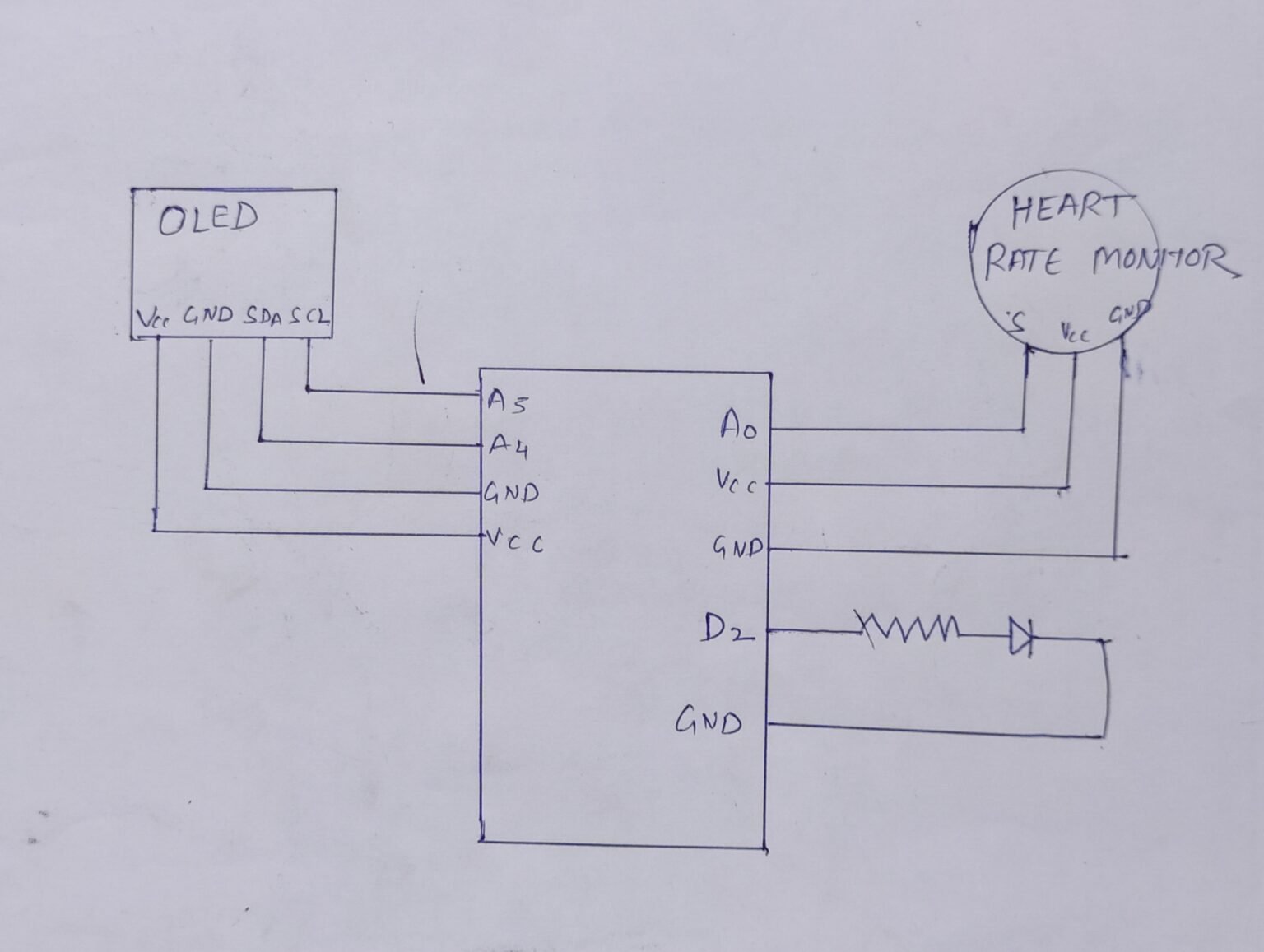
How to make Heart Rate Monitor Circuit Diagram
BlogHow to make Heart Rate Monitor Circuit Diagram Modify the loop() function to read heart rate and oxygen saturation data from the MAX30102 sensor and display it on the OLED display. Usage. After wiring according to ECAD, upload modified code to the Arduino Mega. Place middle finger of dominant hand on MAX30102 sensor and see heart rate and oxygen saturation readings on OLED.
The MAX30100 sensor is used as both a heart rate monitor and a pulse oximeter. These features are enabled by the construction of this sensor which consists of two LEDs, a photodetector, optimized optics, and low noise signal processing components. Blood oxygen saturation and heart rate are found using these these two key features. We will The purpose of this project was to develop a wireless heart rate monitor based on the principle of photoplethysmography and using the Bluetooth Low Energy (BLE) technology for wireless transfer. result of this project could also be further developed into a prototype of an oximeter that would also measure blood oxygen saturation. Kokoelmat.

Arduino Practical Workshop: MAX30102 Wrist Heart Rate Monitor Circuit Diagram
To measure the Heart Rate, i.e., the beats per minute, that we placed an Infrared Led(980nm) beside a Photodiode, and made it a compact capsule so that they don't move while taking readings, and placed a black cover around them to protect it from ambient light. As soon as we encounter a peak, a timer gets started and measures the transit time
The working of MAX30100 can be divided into two parts: Heart Rate Measurement and Pulse Oximetry (measuring the oxygen level of the blood). Heart Rate Measurement. The oxygenated hemoglobin (HbO2) in the arterial blood has the characteristic of absorbing IR light. The redder the blood (the higher the hemoglobin), the more IR light is absorbed.

How to use an oximeter and heart Circuit Diagram
SparkFun Electronics offers an oximeter and heart-rate monitor sensor, which comes mounted on a small board. Users only need to press a finger on the sensor module for a reading. Communication with an external controller is easily done with an I2C protocol, which is what we use for this project, along with Arduino Nano. Read Heart Rate using MAX30100 and ESP32. To find the heart rate (BPM) and Oxygen Saturation (SpO2) using MAX30100, we will use the I2C communication protocol and display the readings on the serial monitor of Arduino IDE. For the interface, we will use.MAX30100lib by OXullo Intersecans.
