hole vs Surface Mount Components Circuit Diagram
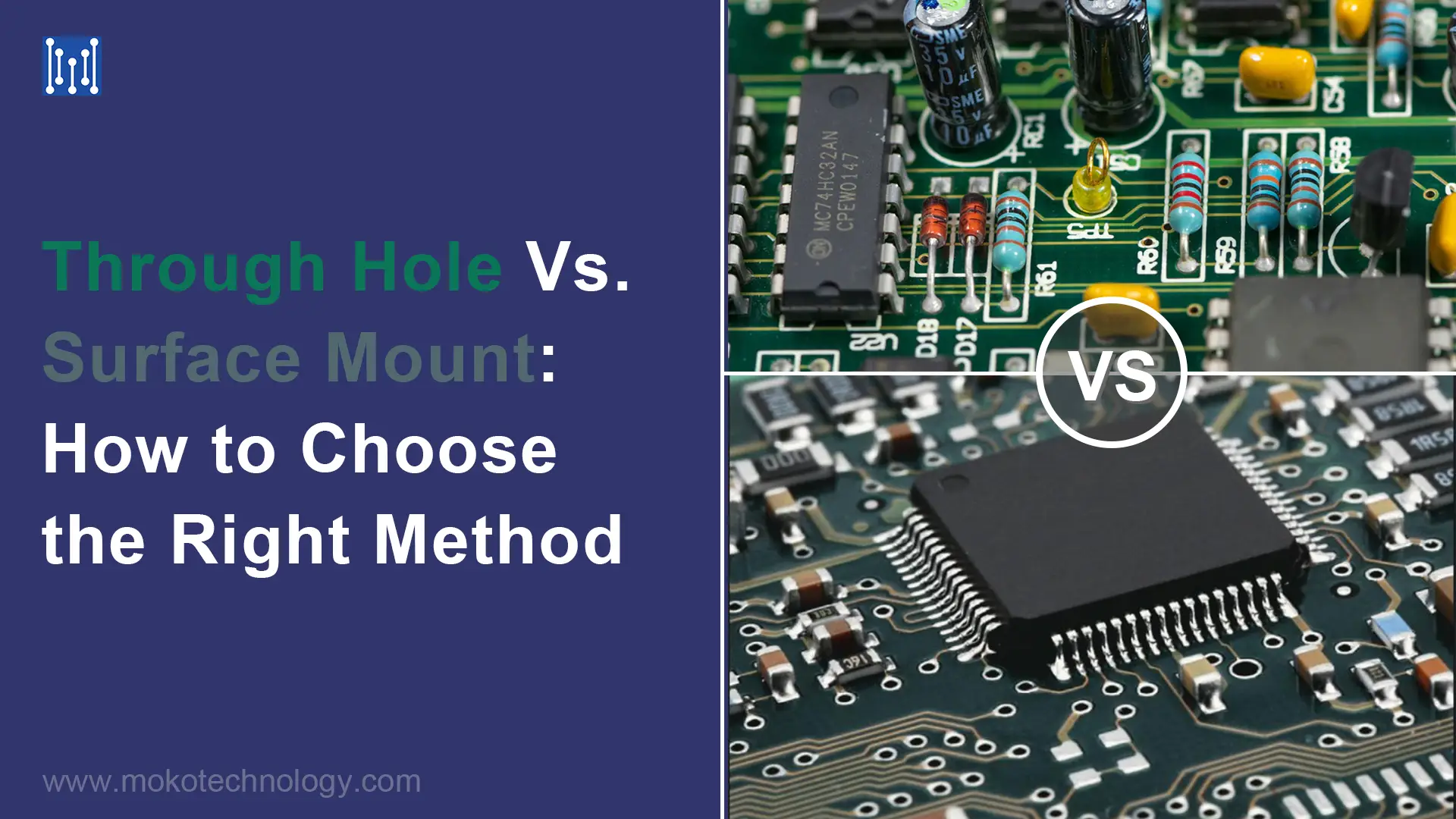
Bloghole vs Surface Mount Components Circuit Diagram Before the emergence of SMT in the 1980s, through-hole technology was the industry-standard configuration method. However, Surface Mount is more efficient and less expensive, it leds many people to believe that THT would become obsolete. Although through-hole components represent the older of the two technologies, there are still valid reasons

Through Hole mounting is inserting component leads into drilled holes in a bare PCB. Before the emergence of SMT in the 1980s, through-hole technology was the industry-standard configuration method. The fact that Surface Mount is more efficient and less expensive has led many to believe that THT will become obsolete.
Surface Mount v. Through-Hole - PCB Manufacturing Circuit Diagram
Surface Mount Technology (SMT) represents a paradigm shift in electronics assembly, enabling the direct placement of components onto the surface of printed circuit boards (PCBs). This method diverged from the traditional through-hole technique by eliminating the need for wire leads to pass through the PCB. There are two leading methods for assembling a board — surface mount technology vs. through-hole technology. Overview of the PCB Assembly Process. The most commonly cited example of thru-hole mounting process benefits is the fact that thru-hole mounted components offer enhanced reliability. Because the leads go all the way through the

Instead, surface mount components are soldered onto pads on the surface of the board. These surface mount components, known as Surface Mount Devices (SMDs), come in a variety of shapes and sizes, but they are generally much smaller than their through-hole counterparts. The SMT process begins with the application of solder paste to the PCB. Key Differences of Through Hole vs Surface Mount. In the through hole versus surface mount debate, knowing the key differences will help you choose the right method for the intended application: More components can be mounted on the board, in part because SMT components are smaller, and in part because both sides of the board can be utilized.

depth Comparison for PCB Component ... Circuit Diagram
The choice between Surface Mount Technology and Through Hole Technology is pivotal in electronics manufacturing. Each method offers distinct advantages and is suited for different applications. By understanding the key differences and evaluating your specific needs, you can optimize your manufacturing process and achieve superior results.